
Additive Manufacturing
Gitbook documentation not finished yet.
For content, please view the notion page.

Assignment
This week we will be design and print 3d models, which is something i've never done before.
Even though I have designed for CNC machines before, I think designing in Fusion360 might be a bit of a challenge for me. The only 3D software i've used before is Unity, which was definitely fun, but very difficult. As you can see in the following video, things like scaling might turn out different than you expect when you're used to 2D objects.
This was also our last week before the school closed, so unfortunately we didn't get the opportunity to remake our prints.
This weeks assignment:
In pairs (partner = Britt de Heer), you will design and print three different molds that can be used in the open material archive.
The aim of these molds is to be able to reproduce material experiments with the same mold but different materials.
These molds should create textural experiments for the casted material.
3D printing
Do I actually need to 3d print?
3D printing is a relatively new technology that was very hyped up by the media at one point. Avoid using 3d printing just to be able to slap this trendy title on your product. There are many downsides to 3D printing, the main one being that it takes a very long time. Take this in consideration when you choose a method to create your object.
Decide on if you want to use formative, subtractive or additive manufacturing based on the amount of objects you need.
The 3d printing process
Decide if 3D printing is the best option.
Decide which material to use.
Producing a 3D file
STL creation and file manipulation
Printing
Removal of prints
Post processing
Struggling with Fusion360
During my time at the CMD major I often had to figure out how programs work on short notice. My usual strategy is to spend only one day on getting to know the basics of the program. Then I assume I know how to do it, and start my project. This usually leads to swearing to my computer and watching a lot of tutorials on Youtube. This time was no exception.
In class we had a short workshop on Fusion360, and it seemed fairly easy. I immediately knew I wanted to make a marble track. Something I almost regretted later. I made a little sketch on what I wanted it to look like.
I didn't feel like drawing at that moment, so I thought this scribble would be enough. It should represent a gutter that spirals down into a square. I thought this design could just be a bunch of ramps that intersected each other. Boy was I wrong.

Connecting ramps
First try. I made a nice gutter by extruding a profile and tilted it to make it a ramp. Then I also wanted the gutter to make a 90º turn. Somehow I thought I could just intersect these two and call it a day. Sadly, the sides of the gutter would block the path for the marble to roll down. I thought I could come up with a way to cut this intersection and remove the walls I didn't need, but this was harder than expected. I didn't really think this through. Let's ditch this method.


Second try. I figured that if i'd just make flat ramps with straight walls, I could shorten certain walls to leave a gap for the marble to pass through. The marble passed through, but the corners were still awkward. The marble technically would fall down, but it just looks very unflattering.


Sweeping a profile along a path
Third try. I looked around the toolbar and found a (seemingly) perfect tool called "sweep". I could sweep the gutter profile from the first try along a spiraled path. Even CAD-expert Kaj had never tried this, approved of this idea. I quickly sketched out the dimensions and got to work.The values are the height of the corners in mm. The green line is the path that has to be drawn.
I tested it on a single path with a corner first, and it worked out well at first sight, so I proceeded to draw out the whole spiral in sketches. This took a hours.
In order to be able to still make these tight corners, the sweep function rotated the profile, which is interesting but not exactly what we were looking for. After hours of getting the initial path in place, this was quite disappointing. I'm not really in control to what happens to the orientation of the profile with the sweep tool, so I decided not to use it.
I'm done with this program
Fourth try. At this point I got very frustrated and was ready to settle for the bare minimum. I accepted that It was hard to make the take corner without a transitional space in between. I decided to to for a simple design that wouldn't look as polished as I initially wanted, but at least it would get a marble rolling. I also chose to first make a test with less windings in the spiral, to see if i'd like the outcome.Another very simple sketch.I had no idea what to do for the start of the track. I 'd also still have to come up with a way to make walls around it.
This design consists of multiple ramps with leveled platforms in the corners.
I figured it would work but I was very unhappy with the result. I missed the semi circular gutter I originally had. I also thought the sharp angles wouldn't make the marble pass through the corner smoothly. I decided to look at my third try again and analyze where it went wrong.
This is when I had my eureka moment.
A modular corner piece.
Fifth try. The problem was clearly that the ramps would not connect well. What we needed was a leveled corner piece. As we saw in the last try. We could still create this leveled corner piece based on the profile of the gutter. Since it's flat, we can reuse it at multiple places in the design.
Now all i'd have to do is connect the corner pieces with the gutters.
A tutorial: How to make a marble track for CNC in Fusion360
This model can be used for CNC drilling or 3D printing in one piece. It fits a regular sized marble (around 12 mm ø)
Step 1. Draw a profile.
Decide what you want the profile of your gutter to look like. I chose a semi circular cutout, but this can be anything you like. Pay attention to the size of the gutter, so the marble you have can pass through.
We want this profile to stay consistent throughout the design. Lock the dimensions by pressing D and selecting the ribs. All the black lines are locked and can't be changed.
Step 2. Create a corner piece.
We want the corner piece to be leveled so we can reuse it for all the corners. Revolve the selected plane 90, using one of the outer ribs as the revolving axis.
Copy and paste this shape until you have ramps enough for your design.
Step 3. Placing the corner pieces.
Think about where you want the corner pieces to be. Put them in the right place on the XY plane. If the corner pieces don't touch, the gutters you create later won't cross each other.
Elevate the corner pieces to the desired height.
Step 4. Create the ramps
We are going to create the ramps with the loft tool. The loft tool generates a transitional body between two sketches.
Note that only one end on the revolved corner piece is a sketch. In order make the other profile side a sketch too, create a plane on the surface of the profile, and project the profile on said plane by holding P and selecting the profile.
Select the two sketches, and use the loft tool. You can find it in the toolbar under
Solid > Create > Loft
Repeat this until you have all the ramps that you need.
Don't delete the sketches after you've created your ramps
You don't have to use the profile of an object to execute the loft, just a sketch will do as well. In my design the track doesn't end on a corner piece. It ends with a straight ramp that ends with the bottom of the gutter on ground level. To achieve this you can place a sketch under ground level and loft. We can remove all the material under the XY plane later.
Step 5. Create a starting point for the marbles
If you made the gutter profile symmetrical, you can create a leveled rounded starting piece like I did. You could also use this as an end piece.
Project the profile of your corner ramp onto a new sketch. Add a line down the exact middle of your gutter shape.
Select the part you want to revolve, and revolve 180º using the middle rib as the revolving axis.
Step 6. Create support.
Since this model is for for the 3d printer the ramps cant just be floating in space. We need to create support, and we have to make sure the bottom is leveled.
Select the (leveled) bottom profiles of the corner pieces. Extrude them downwards. Extrude to the extent of an object. Choose the XY plane in the origin as the object to extent to.
I had a hard time adjusting the height of the corner pieces after i finished the design. I used the join body operation, but in the future i'd rather use the new body method, so I can remove the support without removing the gutter as well.
If we'd extrude the bottom profiles of the ramps the same way, they would extrude at an angle and not straight down. We have to take a different approach for those.
Create a sketch on the XY plane. Project the profile of the undersides of the ramps to this sketch. Now that you have a rectangle thats exactly under your ramp, extrude this shape upwards to the extent of the ramp.
Remember that last ramp? Part of the shape is still under the XY plane. We can cut this away by creating a sketch on the XY plane, extrude it downwards and use "cut" as the operation. Everything within the extrusion will be deleted.
Step 7. Close any gaps.
Because we have rounded corners there are some awkward gaps in the design. This can cause some trouble if you want to make this model on a CNC drill, or if you plan on making a cast out if the model.
Locate the gap in your model, and select the two inner ribs of he gutter.
Go to the toolbar and create a plane that crosses these two ribs
Construct > Plane Through Two Edges
Extrude a sketch on the XY plane upward to the extent of the plane you just created, just like we did for the ramp.
Do this for every gap in your design.
If the planes are obstructing your view, you can hide them in the browser. Do not delete them, the extrusion is related to the planes.
End result
I liked the end result, but in hindsight its higher than necessary, so it costs quite a lot of material. This could be fixed easily if I didn't join all the support to the gutters and corner pieces. I might go back and change this later. I also don't really like that the rounded corner pieces leave such big gaps. so i might come up with something different.
Printing
After putting blood sweat and tears into designing this design it was finally time to print it. We printed it at a 0.2 mm profile with 15% infill. For the material Britt and I chose fluorescent yellow and semi translucent PLA. The other object in there is a 3 piece mold of a skull that we wanted to print simultaneously to save time.
Our mistake: In Cura we looked at the amount of PLA we needed to have, which was around 10m . The roll was almost empty, but more than 10m so we figured we'd be good. We uploaded the file to the printer, but a few layers in we realized we accidentally set the infill to 0%. We changed the infill and forgot to remeasure the amount of material that was necessary to complete the print. But it's not a total waste, since we can now take a look at the infill and the overall quality of the print.
Since I didn't want to come to the show & tell session empty handed. I quickly printed a tiny low quality version. And unfortunately Murphy's law also applied here.0.4mm nozzle, 0.2mm profile, 5% infill
Because I wanted the print to be done as fast as possible, so I thought id make the infill very low so there would be less material to print. Unfortunately this didn't create enough support at certain places. Some corners are caved in and there were a few burnt pieces of material that stuck to the nozzle. I did however just print this to have something physical to bring to show & tell, so at least it has served that purpose. I might be able to roll a bearing ball down this track, but I couldn't find one to test it out.
Making a mold
Part of the assignment was to make a 2.5D mold that we could cast later.
The process
Print the object on the 3D printer.
Vacuform the 3D object to make a mold.
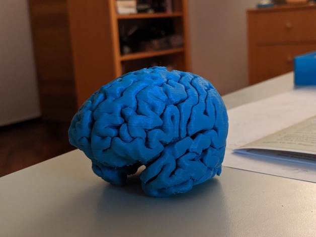
Britt found a model of brains, which she cut in half in Fusion360. We cut it in half so it would sit flat on the vacuform bed, and so it would be easy to remove out of the mold. We used gold PLA, printed with a 0.4mm nozzle, 0.2mm profile and 10% infill. Unfortunately the printing bed shifted maybe half a millimeter, so there is a slight "glitch" in one of the middle layers, but it's almost unnoticeable.
Beforehand we knew this was a tricky shape for the vacuformer, but we decided to go for it anyway. Initially we thought we could use a regular polystyrene sheet, and don't suck all the air out so it wouldn't get stuck in the crevices. Henk the lab tech told us this is probably not a good idea. He strongly suspected that the object was never going to release from the mold. He gave us a sheet of 1mm EVA foam instead , because if the material of the mold is flexible the object can almost always be released.
The formed mold was very detailed, you could even see the printing layers on the inside. The foam wasn't sucked into every crevice of the brain, but this was ok for our purpose. It might be a bit challenging to cast this mold, because it's quite flexible, but we will worry about this later and i'm sure we can find something that works by that time.
Reflection
The first few tries I messed up because I didn't think about the design too much. I had a vague image in my mind, and this was obviously not enough. This is especially not enough if your spacial awareness is not very well (like mine). I have no problem when designing a flat object that folds into a 3D object but I had a hard time understanding how the ramps would intersect when they're tilted on multiple axis. My visualizations were poor too, I could have prevented the first few fails by drawing them out, but since i'm not really good at drawing in perspective I think it's not worth the time to make a 3D sketch on paper. In the future I might use another medium as a first physical prototype, like legos or clay. It's faster and I will get a better understanding of shapes.
For the brains Britt and I got a little too excited about 3D printing, and we chose very difficult shapes for our molds. They were way too complex to model ourselves after a short workshop about 3D modeling, so after struggling for quite a while we chose existing models and manipulated them, but they were never meant for the exact purpose. I wish we had more time to learn how to use Fusion360, so we could
I did enjoy using Fusion360 a lot, but there are many different approaches to the same problems. It sometimes was a bit overwhelming to sit besides multiple people who are interested in what i'm doing, cause I got a little overwhelmed by the advice. I think i'll work on my own a little more often.
Class discussion
📖
This week's Zine: Reflect on what your responsibilities are as a maker/designer for making objects and the impact they have on people, society and the environment. Create your own manifesto. Discuss how you used this in your process this week, and how it's (an aspect of) your work. 150 words and a visual.
🖨
How does a 3d printer work? From file to machine.
🗑
Will people still use it? Probably not. Maybe we could make community 3d printers more accessible. Maybe even a mail service?
🏗
As a consumer, is it necessary for us to create products? Make not only products, but also tools yourself. Custom products fast and (relatively cheap), produced on site.
💼
Creative commons license. Who can use my files and work? What is a difference between a patent and a license?
⚡
Why disruptive? A shortcut from the normal steps to have an object made.
🛠
When and why would you choose to 3d print? When the part we need is unavailable.
🔫
Making bad products.You can also make weapons. Do we want this to happen? What is a bad product?
💼
How to patent a 3d printed object? Do you patent the file? Do you patent the shape?
📜
The maker's bill of rights. Is this a bunch of bullshit or not?
Zine text - A bunch of broken devices
In my life I have owned 6 smartphones, which means that the average lifespan of my phones is about a year. I am a clumsy person and I use my phone all the time which will lead to the inevitable breaking of my device from time to time. Especially nowadays when brands keep pushing the prices of their flagship models to the limit, I cannot simply afford a new one. Out of necessity (and slight curiosity) I started repairing my own devices.
It is the year 2014. I dropped my first budget Samsung model in the toilet. The rice trick wasn't common knowledge yet, so immediately I snapped open my phone, took the battery out and wrapped it in toilet paper in hopes of saving it. To no avail. I googled for a bit, and with the screwdrivers I had lying around my house and a toothbrush I got my phone to work again.
2015 comes around. When the iPhone 6 released I bought my friend's old iPhone 4. I dropped it on the bathroom floor. Yes it was the one with the glass back, and I broke it (why did they make it out of glass in the first place). For €10 I found a new back cover online. This time around it wasn't as easy as the Samsung. They shipped 5 point star screwdriver with the parts, otherwise I couldn't open it.
After these instances I repaired a few more of my phones. Throughout the years it had become harder and harder to replace certain parts, from broken audio jacks to home buttons. I had to order more obscure tools like screwdrivers, guitar picks and suction cups to try to open up these devices. I had to scrape away glue. I had to melt off certain parts with a heat gun. It was a fight against these devices to repair them.
Last December. I was at a party. By this time I had my OnePlus 5t for two years. It was expensive (for me) and I want to make it as last as long as possible. I have a history of dropping my phones and therefore buy my screen protectors by the dozen. I dropped it from a height of 2 meters and the touch screen stopped working. There is not a screw in sight on this device and I already know that there will be about 5 oddly shaped bolts inside that I can't unscrew. Defeated I brought my phone to the repair shop. Where they charged me €130 for a new AMOLED screen. A slap in the face for a college student.
Now I proudly present all my broken phones in my room on a shelf. As a reminder that I should be careful with my devices, because the days that I can repair them myself are in the past now.My shelf of broken devices. Not just smartphones, but also half a MacBook and a magic mouse (the amount of broken apple products in my collection is... interesting).
Last updated